
For ultra precision laser application with processing area bigger than available in a two dimension mark field size, XY linear stages are used. These linear stages with linear encoders can give sub-micron accuracy. However they have to be calibrated carefully preferably in-situ with laser interferometers and the offset errors entered into compensation tables in each stage’s controller. The data is also most precise at calibration temperature so the machine should be housed in a temperature stabilized room. This is usually a clean room with temperature and humidity control. Solid floor foundation is also required for vibration free environment. As a standard practise, passive rubber absorbers are designed into our machines. There are cases where extra high precision or large tables with huge masses like granites is requirement. For these and also for machines with fast dynamic movements, active stabilisation platforms are used to dampen vibrations quickly and also to act as buffer against peak dynamic forces during acceleration/deceleration. Example case is like large glass panel marking.

Besides single stage error compensation, 2 dimension position error compensation is equally important, meaning the orthogonality of the two stages. However this correction table is difficult to obtain. In our case we use precision glass jig to measure this error. The glass jig has ruler ticks over it’s full surface. The glass jigs which we also use for calibrating our scanvision products come in different sizes and are manufactured in wafer foundries. The glass jig is placed on the XY stage and moved to different positions. A camera captures the zoomed in image of the glass jig and each position is read accurately. The errors are then entered into two dimension compensation tables in the XY stage controller.
For Z flatness over the whole XY envelop, the zoom camera is again used to focussed on a regular matrix of positions. As the processing chuck is mounted on a precision Z stage, using image processing focus finding software, we can use an automatic routine to run through a matrix of positions covering the XY stage and save the list of height errors. A 3 axis interpolation method is then used to derive the best x, y & z during processing.
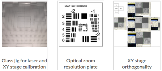
The zoom camera has to be aligned too for perpendicularity and angular straightness to the XY stage plane. This is done by using a precision optical pattern plate. The calibration regime can be onerous and laborious but is necessary to obtain best precision result for the whole work area. Using software, the process can be made as automatic as possible to save manpower and time.
Besides the linear stages, other technics had to be devised to improve the accuracy of the scanhead. This was done by adding an additional compensation table into the galvo movement calculation during translation from the ideal coordinates to the physical coordinates. This was made possible as we developed and own the scanhead marking software. The table was used to do an interpolation between 4 measured corners enclosing a target point. The table was generated from firing the laser to mark a matrix of dots on a substrate placed on the XY stage and then moving the XY stage to each target point and measuring the deviation using the zoom camera. A number of dots in a FOV were measured together to reduce the time required to complete the calibration.